STIRLING ENGINE
ME 200 Team 22
Prototype Schematic
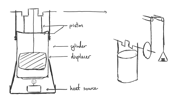
Our Stirling engine will be powered by a single tea candle as the heat source. The cylinder of the engine will be made from an aluminum can that has its top cut open. A displacer made from a porous scour pad will be fitted in the cylinder to mix hot air and cold air.
Attached on the exterior of the aluminum can will be two struts made from popsicle sticks, which support the crankshaft. The crankshaft is driven by a piston which attaches to a balloon wrapped over the top of the aluminum can cylinder. The balloon is reinforced with a circular cutout of cardboard to maintain a flat profile.
The crankshaft, in turn, pulls on the displacer, which is connected by a string. The crankshaft is designed such that the motion of the piston is out of phase with that of the displacer, which is how the Stirling engine operates.
Once the Stirling engine begins operation, a flywheel connected to the crankshaft will turn and wind up a string connected to a pulley system that holds the quarters. This process will raise the quarters up to 2 meters.
Prototype 1

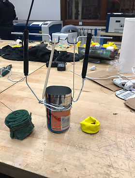

Our first prototype was constructed to identify flaws in the conceptual design prior to committing to a refined version. Four major issues were identified:
-
Heat conductivity of the aluminum can causes air in the upper section of the cylinder to heat up rapidly, resulting in inefficient heat transfer and rapid loss of power.
-
The balloon was too tight/small to allow sufficient piston travel. It also caused warping on the aluminum can due to the thinness of the can's aluminum walls.
-
The crankshaft displacements were too large and demanded too much travel distance from the piston, causing the overall structure to buckle.
-
The displacer was a major source of friction, both from brushing against the aluminum can walls as well as from the string brushing against the piston.
How do we improve?
In between our first main prototype and the second, we carefully reevaluated the current status of each main part in our design to determine how each might be improved. We considered changes in material, orientation, and other methods to improve quality and function. We placed a lot of emphasis on creativity and thinking of unconventional ways to improve the efficiency of our engine. As a result, Prototype 2 appears much more refined and with much more carefully oriented components.
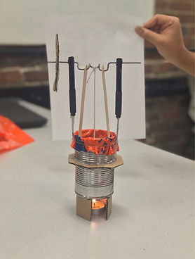
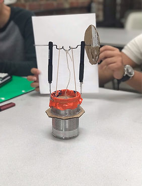
Prototype 2

Bill of Materials
Our second design significantly improved from the first. The aluminum can was replaced with a sturdier option, and was cut in half to allow cardboard ring to serve as thermal insulation between the upper and lower sections of the cylinder. The crankshaft was reworked and travel distance was reduced. The balloon was replaced with a plastic bag with more slack, and the size of the displacer was reduced by replacing the original scouring pad with iron wool.
This version of the Stirling engine was able to rotate much more freely and was subject to significantly less friction. However, improper sizing between the crankshaft and piston still caused issues with travel distance. The hole cut out in the piston to allow the displacer to be connected to the crankshaft was too large and caused air to leak quickly.
(x1) Coat Hanger Wire
(x2) Pen Casing
(x2) Popsicle Sticks
(x1) Cardboard Ring
(x2) Cardboard Plate
(x1) Cardboard Stand
(x1) Iron Wool
(x1) Thin String
(x1) Plastic Bag
(x1) Aluminum Can
(x1) Tea Candle
--->
--->
--->
--->
--->
--->
--->
--->
--->
--->
--->
Crankshaft
Struts for Crankshaft
Struts for Piston
Thermal Insulator
Flywheel; Piston
Base
Displacer
Connector for Displacer
Piston Air Seal
Engine Cylinder
Heat Source
* The total cost of materials for this project is under $10.
Inspiration
Where to next?
We've honed in on creative ways to improve our design from initial concept sketch to a tangible design that is extremely close to working. Highlights include:
- Using a much sturdier cylindrical housing for the working fluid to operate in
- Exploring a unique method to insulating the top and bottom half of the can.
- The crankshaft was carefully re-molded with more accurate dimensions
- The displacer material was changed to a lightweight form of steel wool
- The Piston Air Seal was replaced by an flexible plastic seal which added lightweight elasticity.
In the "Future Improvement" section we will further examine the state of our second and final prototype, including all potential improvements that we would make if we had more time and resources available.